


Diagnosing and disabling bugged CPU cores
Yesterday my CPU died: constant reboots, BSODs, freezes, etc. Usually I would buy new hardware, but I couldn’t waste time with that just yet, so I managed to find out what exactly was failing and how to avoid it. Most people won’t bother with this kind of stuff, but I thought I should document the process I followed; it might be of help to someone, some day.
Disclaimer: I’m stuck with Windows OS for various reasons, so if you use any of the OS master races, half of this stuff will be useless I’m afraid.
- First of all, make sure the reboots are due to CPU issues. For that, follow the usual procedure: unplug all devices you don’t need, test your ram, yada yada

- Download prime95, open it, choose 1 torture test thread, choose Small FFTs option, and don’t click “OK” just yet (or you risk an insta-BSOD)
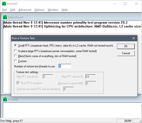
- Go to task manager, click More details, go to Details tab, locate and right click on prime95 process, click “Set affinity”, uncheck all CPUs except the first one.

- Go back to prime95, click OK to start the test on that one core. Let it run for 5 minutes. If any numeric error or warning message shows up, it freezes, it ends in BSOD, etc, then that core is probably busted.
- Repeat the test choosing different affinities, this will test a different core each time.
- After that, I would also test pairs of cores. Hyperthreading, shared-FPUs, shared L2, heat dissipation problems, etc, can all lead to failures only when several cores are used at the same time.For that, your best bet is to test with affinity set to consecutive pairs of cores, and then adjusting the number of threads in prime95 accordingly.
In my case, this yielded problems in the 5th and 6th core (always failing when used in conjunction, and rarely when run in isolation). I would bet the problem is their shared FPU path, but I have no idea how to find out for sure.
Once you have determined the failing core or cores, you can survive without a new CPU this way:
- If your BIOS allows it, look for the option to selectively disable cores. My mobo allows disabling pairs of cores rather than individual ones, but that was okay in my case, since I had to nuke one of those pairs.
- If that’s not possible, hit Win+R, run msconfig, go to Boot tab, click Advanced Options, mark “Number of processors”, and choose the appropriate amount. You will probably lose some working cores, but it’s something ¯\_(ツ)_/¯
And of course, if you can afford the wait, just throw that CPU away and buy new parts. Otherwise your CPU will be limping around… and the rest of cores are likely to follow the same path anyway.
Hacking the LGA 775 socket
Hello, and welcome to CPU Dealers!
In todays episode we’re going to learn how to fit an LGA771 CPU into an LGA775 motherboard with no brute force!
Motivation
So why on earth would anyone decide to put an LGA771 Xeon server cpu into a domestic LGA775 motherboard, you may ask?
Welp, because it’s fun and you get to learn stuff, thats why!
Traditional motivation: Money
However, the usual argument is that, if you are planning a modest upgrade for your shitty old LGA775 system, not needing the latest and greatest, you can save some money this way. See, there’s lots of Xeon processors in the market right now, and they are all dirt cheap. The interesting thing is that most LGA775 CPUs have Xeons equivalents:

The Xeon I chose, an E5440 SLBBJ. Same speed as a Q9550, but requires less juice, so has a lower TDP. Source: here and there.
Some people argue that Intel simply bins Xeons better than the consumer counterparts, so while being essentially the same CPU, the Xeons are more reliable, run colder, and are harder, better, faster, stronger.
The LGA775 market, on the other hand, is filled with pretty expensive CPUs. They’re all usually priced 30€ to 150€ higher than the server versions: Xeons are definitely the best bang for the buck. So the plan usually is:
- Upgrade your system to a Xeon instead of a domestic CPU.
- …
- Fun and profit!
Side motivation: Overclocking
Some people take advantage of the lower voltages required by Xeons, and choose them not only because they’re cheaper, but because it’s in theory easier to squeeze a bit more speed out of them.
Keeping that in mind, I chose an E0 stepping (later revisions usually lower power requirements of the CPU). Unfortunately, my SLBBJ unit was already running pretty hot at stock voltages and clocks, so I’m leaving it alone for the time being.
Background
LGA775 (codenamed Socket T) was introduced by Intel around mid-2004, and used in domestic motherboards. The most popular CPUs running those LGAs are now Core2Duos and Core2Quads.
A year and a half later, in 2006, Intel introduced LGA771, a very similar LGA intended for use in multiprocessor server motherboards, and which can host Intel Xeon processors.
Looking at the official datasheets released by Intel (page 41 here and page 52 here) , we can check the pinouts of both LGAs, and spot their differences:
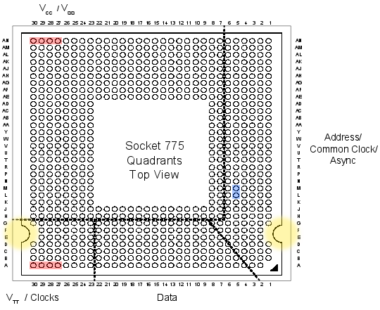
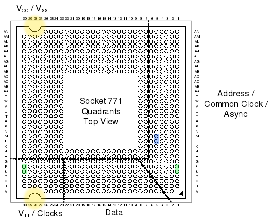
If we checked the socket pin assignment one by one, we could see that there’s 76 different pins in total. But most of them are irrelevant (reserved for future uses, etc), they pose no problem for our conversion mod, so we’re left wondering about the colored pins:
- Red: 8 pins only used in LGA775.
- Green: 4 pins only used in LGA771.
The red and green pins are all power pins (VCC, VSS at the top, and VTT at the bottom). There’s hundreds more of them in the LGA, so I’m sure our new CPU won’t mind if we remove just these few.
- Blue: 2 pins that have different purposes in each LGA.
These pins (L5 and M5) serve different purposes in LGA775 than in LGA771. And this time they are important pins (one of them is the Execute BIST pin, Built-In Selft Test, needed to boot). Fortunately, Intel had simply swapped their places in the newer 771 LGA! So it should be relatively easy to re-wire them.
- Yellow: not a pin, just highlighting the different shapes 🙂
These differing yellow shapes can be a problem, since the CPUs from one LGA will not physically fit in the other LGA without some hardware modifications. We’ll get to this later on.
Uh, in case you’re wondering, I did not personally go over all the pin specifications one by one. But this guy did.
Motherboard support
In most cases, the CPU will run as-is. This was the case of my 965P-DS3 motherboard.
Sometimes, you may need to manually patch your BIOS, adding the microcode of your specific Xeon model to the internal “whitelist” (so to speak). Additionally, this usually forces your mobo to acknowledge that your Xeon CPU implements the SSE4 instruction set (which can give an extra speed boost in some applications).

I didn’t patch my BIOS just yet… so instead, I decided to steal this screenshot from Google Images. Sue me.
And in a few rare cases, your motherboard will directly refuse to boot the new CPU, regardless of any BIOS patching you may attempt. In that case, you’re out of luck.
Before attempting to transform your LGA775, search the web and check if your chipset will be happy with a Xeon CPU.
In any case, bear in mind that your mobo needs to support the speeds that your specific Xeon choice requires: voltage, FSB speeds, etc. Otherwise you’ll have to resort to underclocking the CPU (sad), or to overclocking your motherboard/ram (yay! but not recommended).
Procedure
First, open your tower, remove the heatsink, then the CPU:

There lies my old Core2Duo E4300, overclocked to hell, ready for retirement.
Now we do what the title says: we hack the LGA775 socket. Literally.
Yes, take a sharp knife or a cutter, and prepare to slash some plastic. The exact bits you have to cut off are the ones colored yellow in the LGA775 pinout diagram (scroll back to the beginning of this post). It should end up looking something like this:

Actually, please try to aim for cleaner cuts than the mess you see in this photo.
The motherboard is ready!
Now we need to hack the Xeon CPU itself. Remember the blue pins that had switched places in LGA771? It’s time to revert what Intel did, and get a 775-compatible pinout layout.
If you’re good enough you could try to swap them yourself, using whatever technique you come up with. But the rest of us mortals will resort to buying a ready to use swapper sticker. Search for “775 771 mod” in ebay, play safe and buy several of them, just in case you break one in the process:

Be very careful with the sticker, it’s very easy to break its internal wiring.
So there’s that. Now we simply have to put the Xeon in the LGA, add thermal paste, heatsink, etc:

Yay, we’re done!
Finally, plug the PSU, pray to Flying Spaghetti Monster, and boot the system!
Results
Here’s a nice comparison graph of the results. The contenders are:
- A Core2Duo E4300 (LGA775), at speeds ranging from 1.8GHz (stock) up to 3.01GHz (overclocked).
- A Xeon E5440 (LGA771), at stock speed (2.83GHz).
The benchmarks are:
- Assetto Corsa, a multithreaded racing simulator (M30 Gr.A Special Event), FPS measured with my own plugin FramerateWatcher.
- PI calculator SuperPI, 2M variant, running in a single thread.
- Average maximum temperature reached by all cores, over a period of 15 minutes running In-place large FFTs torture test in Prime95.

And the winner is…
The winner is the Xeon, as it should: specially in multithreaded programs, the Xeon obliterates the Core2Duo.
But it’s interesting to note that, even running at the same clock speed of around 2.8GHz, the Xeon outperforms the Core2Duo by more than 20% in single threaded applications.
I checked the FSB and RAM multipliers in both cases, just in case the Xeon had an advantage on that front, but it was actually the E4300 which had higher FSB and RAM clocks!
Goes to show how clock isn’t everything when it comes to performance, and obviously better CPU technology consists of more than higher clock freq and greater number of cores.
The end
So that’s it, that’s the story of how I more than doubled the framerates in games and halved compilation times for the cost of 4 movie tickets.
Hope you enjoyed reading this article as much as I definitely did not enjoy proof-reading it! 😉
06.18.12Software steadicam – Or how to fix bad cameramen
So you’ve just come back from vacations (wohoo), having filled 10 gigs of photos and video, only to discover you’re a (let’s be honest here) shitty cameraman without your tripod?
Fret not, for this article will show you the secret to solve your problems!
In an ideal world, your hands are as steady as a rock, and you get Hollywood quality takes. In the real world, however, your clumsy hands could use a hand (hah!).
So here’s your two main options:
Hardware solution (for use while filming)
This is the proper solution: a system that will compensate for the vibration of your shaky hands and the movement of your body while walking – not unlike the springs on your car allow for a pretty comfortable ride through all sorts of bumps.
Ideally, it will compensate for all the 6 axis (3D traslation + 3D rotation), but in practice you may be limited to less than that. Unfortunately (for most), this depends on how deep your pockets are (buying a ready-to-use steadicam, ranging from 100 bucks to several thousand), or on how handy you are with your toolbox (building a home-built equivalent).
The result could (in theory) be similar to this:
(ah, yeah… a segway, minor detail)
Software solution (for use after filming):
If you can’t spare a segway + a steadycam backpack, there are affordable alternatives. And if you already have many shaking, blurry videos lying on your hard disk, then this is your only option!
We’ll rely on PC software to fix those videos. This, you can do for free at home. There are some payware software packages that may produce slightly better results: but what I’m going to show you is freeware, very quick to use, and good enough quality for most purposes.
The software method may not be that good when compared to an actual steadicam, but hey, it’s better than nothing!
The steps:
I’m not going to go much into details, so here’s the basics.
- Download VirtualDUB, an open source and free video editing software.
(Make sure you can open your videos. E.g. you may need to install the ffdshow-tryout codecs and set them up, or whatever; Google is your friend! 🙂 ) - Once you can open your videos, you have to download the magic piece of the puzzle: Deshaker.
(This free tool – though unfortunately not open source – will do all the important work) - Now open your video, add the Deshaker video filter, choosing “Pass 1“.
(If you have a rolling shutter camera (most likely), and know its speed (unlikely), you can also correct it by entering the necessary values in there) - Click OK, and play the video through.
(This will gather information about motion vectors and similar stuff, in order to find out how to correct the shaking, if present) - Now edit the Deshaker video filter settings again, and choose “Pass 2“. Tweak settings at will, and click OK.
(A progress window will be visible for just a few moments) - Finally, export the resulting video, and you’re good to go!
For a more detailed guide (including rolling shutter values for some cameras), just read the official Deshaker page, or browse Youtube; there’re some tutorials there too.
The settings basically tune the detection of camera movement, as well as what method will deal with the parts of the image that are left empty after deshaking.
The results:
The video below is an example I’ve cooked for you. Each of the 3 processed videos uses a different combination of settings, and was created in no more than 20 minutes each.
I sticked them all together for your viewing pleasure. The improvement can be easily appreciated!
That’s it. Happy filming! 8)
Bonus track
If you insist on using hardware solutions (good!), here’s a neat little trick that’ll allow some smooth panning (provided you’re not walking):
09.2.09hoygan, no puedo resizear las afotos, cómo ago!
Hay momentos en la vida en que pringar puede ser divertido. Por supuesto, se trata de cuando alguien te ruegadeja migrar su apestoso Microsoft Windows Whatever (TM) a Linux.
En su primeras horas de contacto con una Ubuntu 9.04 recién instalada, mi querida aikurushii se me queja en formato hoygan (que en mala hora se me ocurrió enseñarle) de que en Windows podía redimensionar imágenes con solo hacer click derecho, y ahora en Linux no, y que Linux apesta.
Como acto reflejo, me calzo un ssh a su ordenador, y esgrimiendo vim a dos manos le esbozo un bash en 5 minutos:
#!/bin/bash
size=$(echo "$0" |sed "s/.*\.\(.*\)\.sh/\1/g")
for i in "$@"
do
        newname="$(echo "$i" |sed "s/\.\(...\)$/.$size.\1/g")"
        cp "$i" "$newname"
        mogrify -resize $size "$newname"
done
text="Resized to $size px wide."
#some optional user interface candy, uncomment at will:
#zenity --info --text "$text"
#echo $text
El script en cuestión se guarda en, por ejemplo, /usr/local/bin/resizer.640.sh, o resizer.1024.sh, o la resolución a la que se quiera redimensionar las imágenes (también se puede symlinkear el script con varios nombres, por supuesto, y cada uno resizeará a un tamaño diferente).
Y por fin, desde el navegador de ficheros de turno, se le dice que abra las imágenes en cuestion con el susodicho script, et voilà, Linux doesn’t suck any more!
Bueno, y entonces es cuando se me ocurre googlear un poco 😀 y encuentro esta cosa llamada NIS… si el caso es reinventar la rueda 😀 😀 😀
12.1.08Bricotuning de audio para un Renault 21 Nevada – part 3
(…continuación de la parte 1 y 2)
Hola amigos atuneros! Me estaba dando pereza, pero por fin llega el tercer y último bricotuning de la serie! Voy a intentar no alargarme mucho, que ya está bien de tanto párrafo pa unos simples altavoces. 😉
Cableado del coche
Debido al lugar donde se iban a colocar los altavoces, nos pareció más comodo tirar cables desde el salpicadero hasta el maletero por los bajos interiores de las puertas.
Lo primero fue pinchar los canales traseros justo antes del conector universal. De esa forma, los woofers son independientes del loro elegido, por lo que en un futuro se podrá cambiar sin complicaciones.

Fue un poco complicado pasar los cables, así que no quiero ni imaginar las virguerías que hará falta hacer en un coche moderno…

Metimos con cuidado cable resistente por cada lateral del coche (uno por altavoz). Van por debajo de las cubiertas de plástico, como se puede intuir en la foto, de forma que no quedan a la vista.
Por suerte, el Nevada es amplio y sus 3 filas de asientos tienen mucha movilidad, asi que no tuvimos problemas para pasar los cables.
Montaje de los soportes y detalles finales
Para evitar cortos e incendios varios, los soportes de altavoz fueron hechos también de madera, a la cual atornillamos los hembras correspondientes a cada altavoz.
Dichos soportes fueron a su vez atornillados a la tapa que da acceso al compartimento de la rueda de recambio. De esta forma, se puede seguir accediendo facilmente a dicha rueda y herramientas cercanas.
Finalmente, compré tapicería de un gris adecuado por unos pocos lerus, y con cuidado forramos ambos altavoces.
Como una imagen vale más que mil palabras, aki tenéis 5000 y pico palabras: 🙄


Una vez estuvo todo en su sitio, di un paseillo al R21 para ver si los altavoces aguantaban al pasar por baches. Todo fue perfect a la primera, asi que no tuve ni que ajustar los muelles de los enganches.
Aparte, retoqué el bias para que los 4 altavoces saturasen a la par con los géneros musicales y ecualizaciones que suelo montar, evitando así quemar los dos delanteros al ser el cuello de botella.
Proyecto concluído!!

Bonus final
Como premio por haber leido todas las explicaciones, os pongo un videocumental que montó Javi tras hacer de paparazzi aquel finde. Por desgracia, la mierda de calidad de youtube no permite apreciar los graves que saca el equipo, pero os aseguro que es más que suficiente para ese habitáculo 😀
Bricotuning de audio para un Renault 21 Nevada – part 2
(…continuación de la parte 1)
Como iba diciendo, estabamos con el diseño de las cajas. Se hicieron bastante profundas para darle más graves al asunto, que es lo que me interesa. Si me diera igual, las cajas podrían haber sido un poco mas pequeñajas y manejables. He aquí algunas capturas del proceso de fabricación:


Atornillamos las tablas entre sí sin ninguna complicación. Después metimos pistola termofusible por el interior de todas las aristas, además de unas hojas adherentes de esponja negra fina en el óvalo donde luego meteríamos a hostias cuidadosamente el altavoz.
El objetivo no es otro que mejorar la hermeticidad de la caja, con la consiguiente mejora en calidad de sonido que teniendo en cuenta dónde se escuchará (en un coche, y además viejuno!), únicamente los audiófilos podrán apreciar 😆 . La cosa quedó tal que así:

Y ahora la parte interesante: el conector de audio y el anclaje de la caja al coche. Los requerimientos son varios:
- Poder utilizar el maletero completo si hace falta.
- Que el conector de audio sea resistente a los meneos que sufrirá con el equipaje yendo y viniendo.
- Que el sistema sea (des)montable en menos de un minuto.
- No necesitar herramientas para el montaje: nada de llaves allen, ni navaja, ni alicates…
- Que sea, además, bonito y barato, por supuesto!
Estuvimos barajando muchas posibilidades. La mayoria descartadas por ser muy caras (por ej. audio enviado por wifi/bluetooth), muy blandengues (por ej. jacks de audio típicos), y muy warras (por ej. dejar conector y cable con holgura, para que no sufran tirones).
Por suerte, como programador que soy tengo la costumbre de intentar eliminar redundancias, y se me ocurrió una idea que cumplía todos los requisitos. Para llevarla a cabo necesitaba un conector poco convencional, que no se puede encontrar en tiendas de audio, como veréis a continuación:

 Comprobamos la conductividad del material elegido con un tester y altavoces.
Atravesamos la base de la caja con dos parejas de tornillos.
Utilizamos de nuevo la termofusible para fijar los cables tierra y positivo a sendos tornillos.
¿Y qué es lo que va al otro lado de estos 4 tornillos? Esto:


En efecto: para qué utilizar un mecanismo para el anclaje del altavoz, y otro diferente para la conexión de audio, cuando podemos utilizar el mismo para ambos? Con un par de simples cierres de puerta y una visagra solucionamos el problema.
Nota: se podría haber tirado corriente eléctrica por la visagra en vez de utilizar un segundo cierre, pero entonces el anclaje quedaría un poco inestable. Así que finalmente decidimos usar esos 2+1 anclajes.
Weno gente, creo que es suficiente por hoy, que ya me he cansado de escribir y subir fotos 😉 , así que otro día continuaré con el brico.
Coming soon: cableado y bricolaje en el Renault 21 – Parte 3!
10.3.08El método de la nevera
¡Hola frikomaníacos!
Bienvenidos otra vez a Frikomanía, el programa para los que a veces se aburren! En la edición de hoy vamos a hablar sobre discos duros y neveras.
Como todos sabemos, solo los blandos hacen backups de sus discos duros, y nosotros no somos blandos. La experiencia nos indica que es mejor esperar a que el disco duro pete. Sólo cuando éste eche humo procederemos a hacer una copia de sus datos.
Así pues, en el frikonsejo de hoy vamos a ver cómo recuperar datos de un disco duro muerto mediante una nevera. Para ello necesitaremos las siguientes herramientas:

- Una bolsa de congelante. Sí, una de esas típicas azules o verdes.
- Una bolsa de aire hermética.
- Un ventilador de Bilbao (aunque con uno de 30cm también debería valer).
- Un trapo que absorba bien la humedad (por ejemplo una toalla o un trapo de cocina limpio).
- Si nuestro ordenador es un sobremesa vertical, un soporte de unos 15cm (una caja, una pila de discos duros, etc.).
- Una nevera que funcione correctamente a temperaturas bajo cero.
- Por último, un disco duro muerto con datos absolutamente críticos. Preferiblemente suena a carraca y al agitarlo se oyen piezas sueltas en su interior.
Una vez dispongamos de todos estos elementos, podemos empezar con las labores de rescate.
Antes de nada, es necesario aclarar que, al contrario de lo que reza la sabiduria popular, los discos duros de hoy en día no están cerrados a cal y canto. Suelen tener alguna pequeña apertura de ventilación, con filtros finos para evitar que entre mierda. Por tanto, el primer paso que vamos a dar es:
Introducimos el disco duro en la bolsa vacía, y la cerramos bien.
En nuestro caso, el objetivo es evitar en la medida de lo posible la condensación de agua en el interior y exterior del disco duro, puesto que el segundo paso es:
Metemos la bolsa con el disco duro en el congelador, y lo dejamos reposar hasta que esté tan frío que duela.
Mientras se enfría, intentaremos aclarar por qué acabamos de dejar un disco duro junto a dos piezas de atún congelado.
La idea básica es contraer el material previamente expandido debido al calor. Tanto los servos como los rodamientos y los circuitos en funcionamiento generan calor. Con la edad, el calor dilata demasiado los componentes, reduciendo la conductividad de las soldaduras. Además de los efectos eléctricos, dicha dilatación puede provocar la desalineación de las cabezas de lectura de los discos. Al congelar el disco duro se revierten y demoran estos efectos, permitiendo leer del disco mientras permanece frío.

Disclaimer: el proceso de congelación y posterior uso del disco duro puede dañarlo hasta dejarlo completamente inútil. Si has sido un blando no debería importarte, porque ya tendrás los datos importantes a salvo. Si en cambio eres un macho de verdad, tienes dos opciones: a) Seguir adelante con este tutorial. b) Irte al rincón de los blandos y pagar grandes sumas de dinero por una recuperacion profesional, en vez de seguir peligrosos frikonsejos en blogs desconocidos. En cualquier caso, la culpa de lo que pase será tuya, y solo tuya.
while (disk.temperature > 0) goto Disclaimer;
Bueno, nuestro disco duro debería estar ya en su punto. Vamos a preparar el entorno de recuperación.
Sacamos un cable de datos y la alimentación para el disco duro, ya sea SATA, IDE, eSATA o una caja conversora USB.
Si hace falta, utilizamos el soporte para no dejar el disco duro colgando. A continuación preparamos la refrigeración adicional:
Colocamos el ventilador bilbaíno apuntando al final del cableado, donde irá colocado nuestro disco duro.
Preparamos la bolsa de hielo rodeándola con el trapo, para evitar humedad.
Ahora llega lo interesante:
Sacamos el disco duro, lo enchufamos al ordenador, y ponemos la bolsa de hielo por encima.
La cosa podría quedar tal que asín (click para ampliar, y perdonad la pésima calidad de la foto):

En mi caso, utilicé una caja USB tanto para el disco fumao como para el backup, de forma que no necesitaba apagar el ordenador, teniendo listo un comando mount + rsync en consola para el siguiente paso:
Copiamos los datos críticos a otro soporte de almacenamiento muy rapidico, antes de que se caliente el bicho de nuevo.
Gracias a toda la ventilación que le hemos metido, el disco debería aguantar alrededor de media hora, tal vez más, suficiente para copiar los datos críticos. Así que con un poco de suerte, terminaremos el día con los datos a salvo y un posapapeles de última generación!
Bueno frikomaníacos, esto ha sido todo por hoy. En el siguiente programa aprenderemos cómo jakear el equispé de nuestros amigos con un bate de baseball, un pañuelo y un frasco de cloroformo.
Hasta la próxima semana! 😀
09.17.08Bricotuning de audio para un Renault 21 Nevada – part 1
Tal como prometía hace unos días, aquí llega la primera parte del bricotuning de altavoces traseros en mi R21.

 Hace ya unos cuantos meses me cayeron del cielo un par de altavoces de 80w rms cada uno (foto derecha). En casa ya tengo suficiente equipo como para que se quejen los vecinos, asi que investigué si podía meterlos en el coche, un R21 Nevada (familiar).
Delante tenía casi recién montados unos Sony XS-F1725 (foto izquierda), que suman 80 watios rms, asi que los 160w adicionales tenían que ir detrás, para dar un poco de apoyo en bajos.
Sumado, el equipo final necesitará picos de 240w, y el equipo Sony CDX-GT414U que tengo montado provee un máximo de solo 200w. Investigué un poco el tema en internet, y viendo cómo nadie se pone de acuerdo sobre infrapotenciación/sobrepotenciación, decidí pasar de etapas e historias, y montar los altavoces a pelo. Con tener un poco de cuidado y oído, no debería dañarse ni el preampli (por exceso carga) ni los altavoces (fundiendo las bobinas por meterle ondas cuadradas tras el pseudoclipping del preampli).
Así que manos a la obra, me bajé del emule unos cuantos planos del coche, con detalles sobre todas las piezas: chasis, carroceria, interiores, etc.

Entre la pésima calidad de los pdfs y mi vagueza de revisarme cientos de planos, decidi subir el coche a Artxanda y abrirlo junto con un colega, Javi, para comprobar visualmente dónde meter los woofers. Desmontamos medio maletero, descubriendo que:
- El hueco cuadrado del chasis a la altura del pilar C es muy pequeño.
- El pilar D no ofrece ni un solo resquicio para poner nada, logicamente.
- La asimetría del chasis por la tapa de combustible arruina cualquier posibilidad de empotrar el altavoz en huecos posteriores al paso de rueda (a menos que pongas cada woofer mirando pa un lao, claro xD).
Dado que me iba a tocar montar los altavoces restando espacio al habitáculo, tenía completa libertad en cuanto a forma y tamaño de las cajas. Me junté de nuevo con Javi (que me ayudo mucho con todo el proyecto en general, gracias tio!), y decidimos unas medidas adecuadas a los altavoces, dando prioridad a los bajos. Lo siguiente fue ir de compras:

El proceso de montaje de las cajas, que como veréis son un poco especiales, lo detallaré en la segunda parte 😉
Stay tuned!

